- 您现在的位置:买卖IC网 > Sheet目录342 > MCP1403T-E/MF (Microchip Technology)IC MOSFET DRIVER 4.5A DUAL 8DFN
MCP1403/4/5
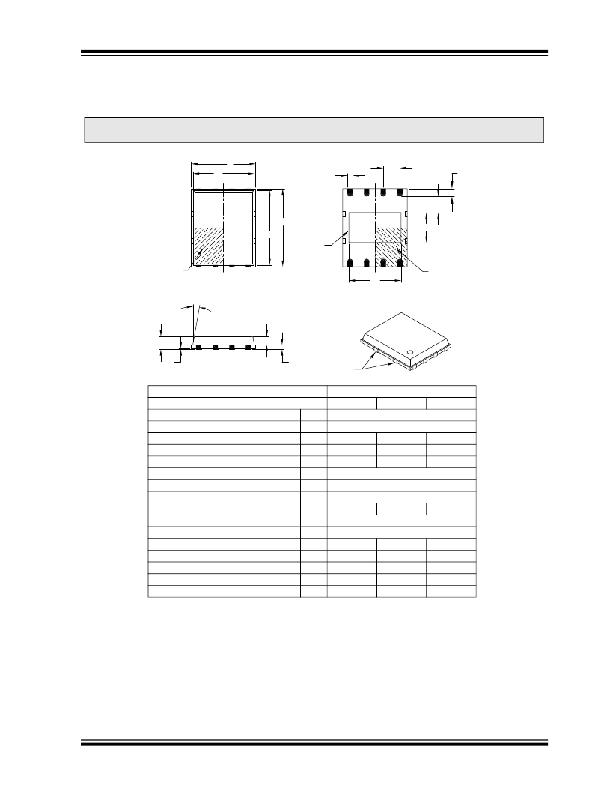
8-Lead Plastic Dual Flat, No Lead Package (MF) – 6x5 mm Body [DFN-S]
PUNCH SINGULATED
Note:
For the most current package drawings, please see the Microchip Packaging Specification located at
http://www.microchip.com/packaging
N
D1
D
b
e
N
L
K
E1
E
EXPOSED
PAD
E2
NOTE 1
1
2
D2
2
1
NOTE 1
A
φ
TOP VIEW
A2
BOTTOM VIEW
A1
A 3
Units
NOTE 2
MILLIMETERS
Number of Pins
Pitch
Dimension Limits
N
e
MIN
NOM
8
1.27 BSC
MAX
Overall Height
Molded Package Thickness
Standoff
Base Thickness
Overall Length
Molded Package Length
Exposed Pad Length
Overall Width
Molded Package Width
Exposed Pad Width
Contact Width
Contact Length
Contact-to-Exposed Pad
Model Draft Angle Top
A
A2
A1
A3
D
D1
D2
E
E1
E2
b
L
K
φ
–
–
0.00
3.85
2.16
0.35
0.50
0.20
–
0.85
0.65
0.01
0.20 REF
4.92 BSC
4.67 BSC
4.00
5.99 BSC
5.74 BSC
2.31
0.40
0.60
–
–
1.00
0.80
0.05
4.15
2.46
0.47
0.75
–
12°
Notes:
1. Pin 1 visual index feature may vary, but must be located within the hatched area.
2. Package may have one or more exposed tie bars at ends.
3. Dimensioning and tolerancing per ASME Y14.5M.
BSC: Basic Dimension. Theoretically exact value shown without tolerances.
REF: Reference Dimension, usually without tolerance, for information purposes only.
Microchip Technology Drawing C04-113B
? 2007 Microchip Technology Inc.
DS22022B-page 13
发布紧急采购,3分钟左右您将得到回复。
相关PDF资料
MCP1406-E/SN
IC MOSFET DVR 6A 8SOIC
MCP14628T-E/MF
IC MOSFET DVR 2A SYNC BUCK 8-DFN
MCP14700T-E/MF
IC MOSFET DRIVER HIGH/LOW 8DFN
MCP14E3T-E/MF
IC MOSFET DVR 4.0A DUAL 8DFN
MCP14E6T-E/MF
IC MOSFET DRIVER 2A 8DFN-S
MCP14E9T-E/MF
IC MOSFET DRIVER 3A 8DFN-S
MCP1640RD-4ABC
BOARD REF DES AAAA BAT BOOST
MCP3906AT-E/SS
IC ENERGY METERING 24SSOP
相关代理商/技术参数
MCP1403T-E/P
制造商:MICROCHIP 制造商全称:Microchip Technology 功能描述:4.5A Dual High-Speed Power MOSFET Drivers
MCP1403T-E/SN
功能描述:功率驱动器IC 4.5A Dual MOSFET Drvr RoHS:否 制造商:Micrel 产品:MOSFET Gate Drivers 类型:Low Cost High or Low Side MOSFET Driver 上升时间: 下降时间: 电源电压-最大:30 V 电源电压-最小:2.75 V 电源电流: 最大功率耗散: 最大工作温度:+ 85 C 安装风格:SMD/SMT 封装 / 箱体:SOIC-8 封装:Tube
MCP1403T-E/SO
功能描述:功率驱动器IC 4.5A Dual MOSFET Drvr RoHS:否 制造商:Micrel 产品:MOSFET Gate Drivers 类型:Low Cost High or Low Side MOSFET Driver 上升时间: 下降时间: 电源电压-最大:30 V 电源电压-最小:2.75 V 电源电流: 最大功率耗散: 最大工作温度:+ 85 C 安装风格:SMD/SMT 封装 / 箱体:SOIC-8 封装:Tube
MCP1404
制造商:MICROCHIP 制造商全称:Microchip Technology 功能描述:4.5A Dual High-Speed Power MOSFET Drivers
MCP1404-E/MF
功能描述:功率驱动器IC 4.5A Dual MOSFET Drvr RoHS:否 制造商:Micrel 产品:MOSFET Gate Drivers 类型:Low Cost High or Low Side MOSFET Driver 上升时间: 下降时间: 电源电压-最大:30 V 电源电压-最小:2.75 V 电源电流: 最大功率耗散: 最大工作温度:+ 85 C 安装风格:SMD/SMT 封装 / 箱体:SOIC-8 封装:Tube
MCP1404-E/P
功能描述:功率驱动器IC 4.5A Dual MOSFET RoHS:否 制造商:Micrel 产品:MOSFET Gate Drivers 类型:Low Cost High or Low Side MOSFET Driver 上升时间: 下降时间: 电源电压-最大:30 V 电源电压-最小:2.75 V 电源电流: 最大功率耗散: 最大工作温度:+ 85 C 安装风格:SMD/SMT 封装 / 箱体:SOIC-8 封装:Tube
MCP1404-E/SN
功能描述:功率驱动器IC 4.5A Dual RoHS:否 制造商:Micrel 产品:MOSFET Gate Drivers 类型:Low Cost High or Low Side MOSFET Driver 上升时间: 下降时间: 电源电压-最大:30 V 电源电压-最小:2.75 V 电源电流: 最大功率耗散: 最大工作温度:+ 85 C 安装风格:SMD/SMT 封装 / 箱体:SOIC-8 封装:Tube
MCP1404-E/SO
功能描述:功率驱动器IC 4.5A Dual MOSFET Driver RoHS:否 制造商:Micrel 产品:MOSFET Gate Drivers 类型:Low Cost High or Low Side MOSFET Driver 上升时间: 下降时间: 电源电压-最大:30 V 电源电压-最小:2.75 V 电源电流: 最大功率耗散: 最大工作温度:+ 85 C 安装风格:SMD/SMT 封装 / 箱体:SOIC-8 封装:Tube
